Got a chance to see my other blogs on MPLS TE? I definitely recommend reading these below two because these will set the stage for this blog.
MPLS TE basic config : GNS3 LAB Cisco : Quick Configuration MPLS TE (traffic engineering).
MPLS TE fast-reroute link protection : GNS3 Cisco LAB : MPLS TE( Traffic-Engineering) FRR (fast-reroute) Link Protection.
Now, let’s get started with node protection. Below is the network and the red path shows that the primary path, however, the node P3 router goes down and node protection is providing the end-to-end path to overcome this failure, see the backup path in green.
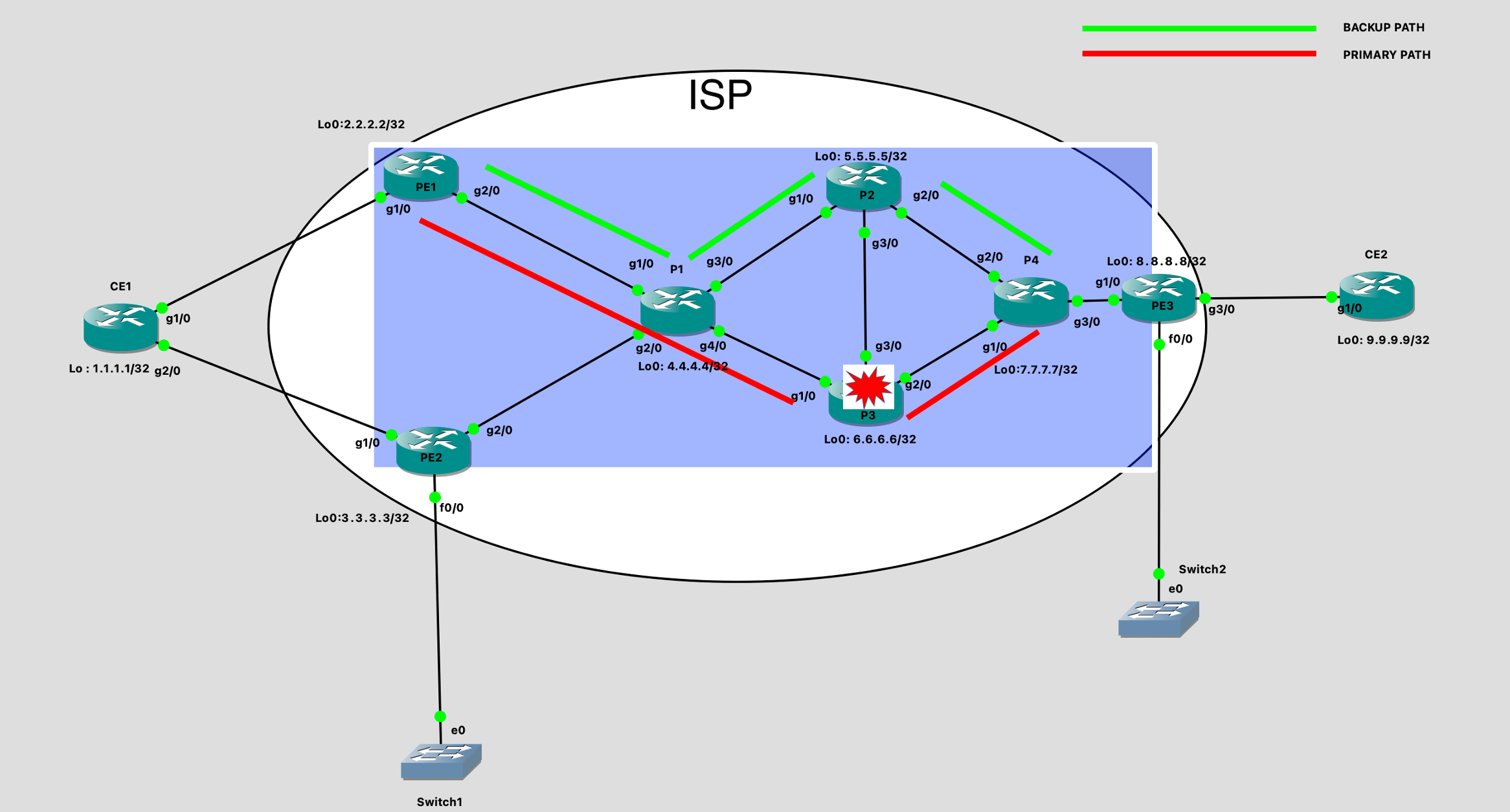
For node protection to work I need to enabled backup node protection tunnels between P1 and P4 which has an alternate path completely unaffected by the failure. Be a little cautious while choosing the alternate path because you may miss some corner scenario and your backup tunnel path gets affected with the failure and the whole Plan B fails. Now let’s see the configs…
Important Note:
for tunnel endpoint and other basic configurations please check my previous blog on this topic. GNS3 LAB Cisco : Quick Configuration MPLS TE (traffic engineering).
Configurations:
P1 Configuration:

!
ip cef
mpls traffic-eng tunnels
!
interface Loopback0
 ip address 4.4.4.4 255.255.255.255
!
interface GigabitEthernet1/0
 ip address 20.20.20.2 255.255.255.252
 mpls traffic-eng tunnels
 ip rsvp bandwidth 512 512
!
interface GigabitEthernet2/0
 ip address 20.20.20.6 255.255.255.252
 mpls traffic-eng tunnels
 ip rsvp bandwidth 512 512
!
interface GigabitEthernet3/0
 ip address 30.30.30.1 255.255.255.252
 mpls traffic-eng tunnels
 ip rsvp bandwidth 512 512
!
interface GigabitEthernet4/0
 ip address 30.30.30.5 255.255.255.252
 mpls traffic-eng tunnels
 mpls traffic-eng backup-path Tunnel100
 ip rsvp bandwidth 512 512
!
router ospf 1
 mpls traffic-eng router-id Loopback0
 mpls traffic-eng area 0
 router-id 4.4.4.4
 network 0.0.0.0 255.255.255.255 area 0
!
interface Tunnel101
 description "Node Protection Tunnel"
 ip unnumbered Loopback0
 tunnel destination 7.7.7.7
 tunnel mode mpls traffic-eng
 tunnel mpls traffic-eng path-option 1 explicit name P1-P2-P4
 no routing dynamic
!
ip explicit-path name P1-P2-P4 enable
 next-address 30.30.30.2
 next-address 40.40.40.2
!


P4 Configurations:
!
ip cef
mpls traffic-eng tunnels
!
interface Loopback0
 ip address 7.7.7.7 255.255.255.255
!
interface GigabitEthernet1/0
 ip address 40.40.40.6 255.255.255.252
 mpls traffic-eng tunnels
 ip rsvp bandwidth 512 512
!
interface GigabitEthernet2/0
 ip address 40.40.40.2 255.255.255.252
 mpls traffic-eng tunnels
 ip rsvp bandwidth 512 512
!
interface GigabitEthernet3/0
 ip address 50.50.50.1 255.255.255.252
 mpls traffic-eng tunnels
 ip rsvp bandwidth 512 512
!
interface Tunnel101
 ip unnumbered Loopback0
 tunnel destination 4.4.4.4
 tunnel mode mpls traffic-eng
 tunnel mpls traffic-eng path-option 1 explicit name P4-P2-P1
 no routing dynamic
!
router ospf 1
 mpls traffic-eng router-id Loopback0
 mpls traffic-eng area 0
 router-id 7.7.7.7
 network 7.7.7.7 0.0.0.0 area 0
 network 40.40.40.2 0.0.0.0 area 0
 network 40.40.40.6 0.0.0.0 area 0
 network 50.50.50.1 0.0.0.0 area 0
!
ip explicit-path name P4-P2-P1 enable
 next-address 40.40.40.1
 next-address 30.30.30.1
!
Verification.
To verify if everything is working fine we will do a two-step procedure.
- We will run some basic verification commands on P1 and PE1 router.
- Also, we will shut down the link gi4/0 on P1, which is the primary path for the tunnel, and check if node protection is working fine. Shutting down the link will make P1 assume that the router P3 is down.
So let’s get started.
The below output tells us following.
- What will be the “in label” for the traffic that I need to protect, here 214.
- Ideally what should be the out label if the backup path is present.
- What will be the label when the FRR tunnel will be “active”, here 501.
- Point to note that label 501 is advertised by P4. And P4 will only ack packets which will be received to it with label 501. Hence we are preserving this label.
- There will be another tunnel label that will be imposed upon 501 for the hop to hop forward over the backup path.
P1#sh mpls traffic-eng fast-reroute database
Headend frr information:
Protected tunnel              In-label Out intf/label   FRR intf/label   Status

LSP midpoint frr information:
LSP identifier                In-label Out intf/label   FRR intf/label   Status
2.2.2.2 13 [30]               214      Gi4/0:414        Tu101:501        ready
You can find out the tunnel label with this output.
P1#sh mpls  traffic-eng tun tun 101

Name: "Node Protection Tunnel"            (Tunnel101) Destination: 7.7.7.7
  Status:
    Admin: up         Oper: up     Path: valid       Signalling: connected
    path option 1, type explicit P1-P2-P4 (Basis for Setup, path weight 2)

  Config Parameters:
    Bandwidth: 0        kbps (Global)  Priority: 7  7   Affinity: 0x0/0xFFFF
    Metric Type: TE (default)
    AutoRoute:  disabled  LockDown: disabled  Loadshare: 0        bw-based
    auto-bw: disabled
  Active Path Option Parameters:
    State: explicit path option 1 is active
    BandwidthOverride: disabled  LockDown: disabled  Verbatim: disabled


  InLabel  :  -
  OutLabel : GigabitEthernet3/0, 301
Also , I happen to capture some debugs and here is a sample debug which you should see on the router where the backup tunnel is configured. This debug will come up as soon as the backup tunnel comes in ready state.
*Mar 16 01:44:51.911: FRR_TUNNEL: tsptun_frr_cfg: Notify GigabitEthernet4/0 driver Protection needed
*Mar 16 01:44:51.919: FRR_TUNNEL: Is backup Tunnel101 safe to use on GigabitEthernet4/0 to next hop 6.6.6.6
*Mar 16 01:44:51.919: FRR_TUNNEL: nnhop Tunnel101 check against 6.6.6.6, 30.30.30.5, 30.30.30.6
*Mar 16 01:44:51.919: FRR_TUNNEL: Tunnel101 (any-unlim) to Destination 7.7.7.7 is safe
*Mar 16 01:44:51.919: FRR_TUNNEL: Using backup Tunnel101
Now, I think this is enough verification. Let’s get into the real action. I will be shutting down the link connected between P1 and P3 to check if the FRR is triggering the backup path. But before that let’s see the traceroute when the FRR is not active.
PE1#traceroute 192.168.2.1
Type escape sequence to abort.
Tracing the route to 192.168.2.1

  1 20.20.20.2 [MPLS: Label 214 Exp 0] 144 msec 100 msec 60 msec
  2 30.30.30.6 [MPLS: Label 414 Exp 0] 68 msec 100 msec 52 msec
  3 40.40.40.6 [MPLS: Label 501 Exp 0] 72 msec 68 msec 88 msec
  4 50.50.50.2 84 msec 80 msec 84 msec
Now shutting down the link.
P1(config)#int gi4/0
P1(config-if)#shutdown

FRR staus changes to active.

P1#  sh mpls traffic-eng fast-reroute database
Headend frr information:
Protected tunnel              In-label Out intf/label   FRR intf/label   Status

LSP midpoint frr information:
LSP identifier                In-label Out intf/label   FRR intf/label   Status
2.2.2.2 13 [30]               214      Gi4/0:414        Tu101:501        active


See the traceroute has also started taking the backup path.

PE1#traceroute 192.168.2.1

Type escape sequence to abort.
Tracing the route to 192.168.2.1

  1 20.20.20.2 [MPLS: Label 214 Exp 0] 160 msec 48 msec 72 msec
  2 30.30.30.2 [MPLS: Labels 301/501 Exp 0] 48 msec 72 msec 56 msec
  3 40.40.40.2 [MPLS: Label 501 Exp 0] 60 msec 80 msec 60 msec
  4 50.50.50.2 56 msec 68 msec 60 msec

Conclusion:
With this article I have documented MPLS TE basics , Link and node protection with FRR . There are some other protection mechanism like path protection , bandwidth protection etc. I will find time to write those as well. But majorly link and node protection are deployed in the ISP networks and you must have a clear understating while troubleshooting it. Once we have setup the core either with basic mpls or mpls traffic engg, it is also important to know the methods to enable services over the core. Like how to connect mpls vpn over TE core. Or how to send multicast over the core. I will be focusing on services in my upcoming blogs. Please follow to get notification of my new blogs. Thanks for visiting.
Check the Youtube video for MPLS TE , FRR Link Protection and Node protection Demo:
very clearly you explained mpls-te here with config …thanks a lot Brother