Convergence time is a problem that humankind is trying to resolve since the day IGPs were discovered. Every vendor keeps on pushing less convergence time. With low “hold time” intervals we somehow manage to decrease the convergence time but this also has a limit, and the chances of raising bigger problems increase when we keep pushing on this limit.
So the only way is to think of a better solution that can work in symphony with the older ways. Where we do not need to push the old classic boundaries and still we can achieve the fastest possible convergence(Traffic rerouting).
LFA and rLFA qualify to be a solution that fulfills the above requirements, this is just a little something that makes your dish sweeter.!!
Lets see some example.
LFA(Loop free alternate):
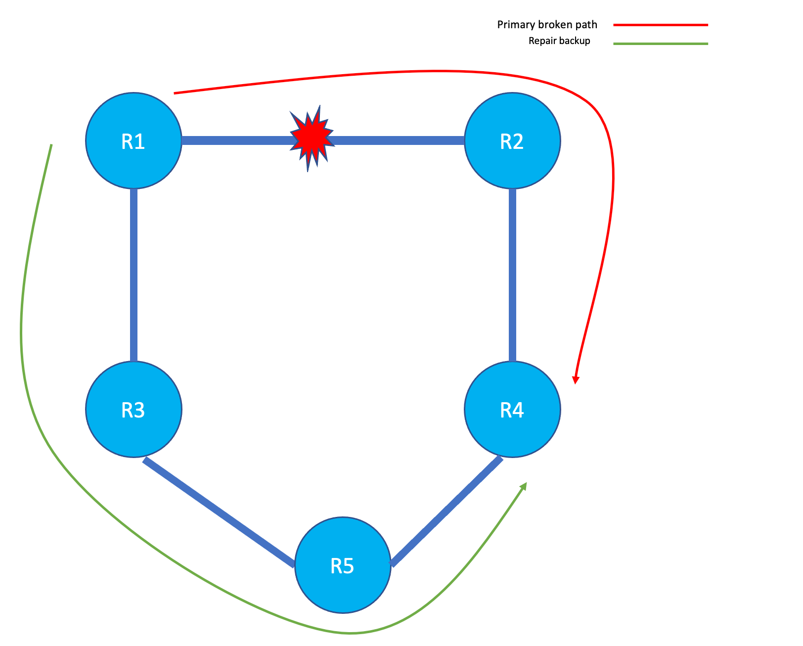
In the following network diag, R1 has a primary path towards R2 to reach a prefix connected on R4. The primary path breaks and ISIS on R1 needs to converge the path towards R3 to reach the prefix on R4. As per the Cisco website, this can take many 100 milliseconds as the path needs to be calculated by ISIS, and then it should update RIB and FIB. Until the path is updated in FIB the traffic destined to that prefix will be dropped. With ISIS fast reroute LFA, the whole path calculation step is skipped and the traffic is just rerouted to a pre-computed path which is always present in the FIB as repair path. Something like below.
R2#sh ip route 6.6.6.6
Routing entry for 6.6.6.4/30
  Known via "isis", distance 115, metric 40, type level-1
  Redistributing via isis CORE
  Last update from 10.10.10.1 on GigabitEthernet1, 00:06:57 ago
  Routing Descriptor Blocks:
  * 10.10.10.1, from 6.6.6.6, 00:06:57 ago, via GigabitEthernet1
      Route metric is 40, traffic share count is 1
      Repair Path: 10.10.10.10, via GigabitEthernet2
Fast-Reroute Configuration:
IOS-XE Devices


!
router isis CORE
 net 49.0000.0000.0001.00
 is-type level-1
 fast-reroute per-prefix level-1 all
!


IOS-XR devices

!

router isis CORE
 is-type level-1
 net 49.0000.0000.0005.00
 address-family ipv4 unicast
 !
 address-family ipv6 unicast
  single-topology
 !
 interface Loopback1
  address-family ipv4 unicast
  !
  address-family ipv6 unicast
  !
 !
 interface GigabitEthernet0/0/0/0
  circuit-type level-1
  point-to-point
  address-family ipv4 unicast
   fast-reroute per-prefix
!
The above configuration is from the R1 node where I have ISIS as IGP. The same FRR can be configured for OSPF as well. You can configure FRR as per-prefix and per-link. The major difference between these two is in terms of resource usage and link utilisation. In case of per-prefix FRR, the backup path calculation is performed for every prefix and it takes more CPU and Memory. In case of a primary link failure, the per-prefix FRR may choose different links for the prefixes which were routed through the primary path so far. For example, if A and B are two prefixes which were using the primary path as of now can now choose two different backup path hence making load sharing possible and doesn’t overwhelm a single backup link, unlike per-link frr. On the other hand, the per-link frr takes less memory and cpu resources as here a bunch of prefixes will have a single link as backup hence it may overwhelm the backup link.
rLFA (Remote LFA):
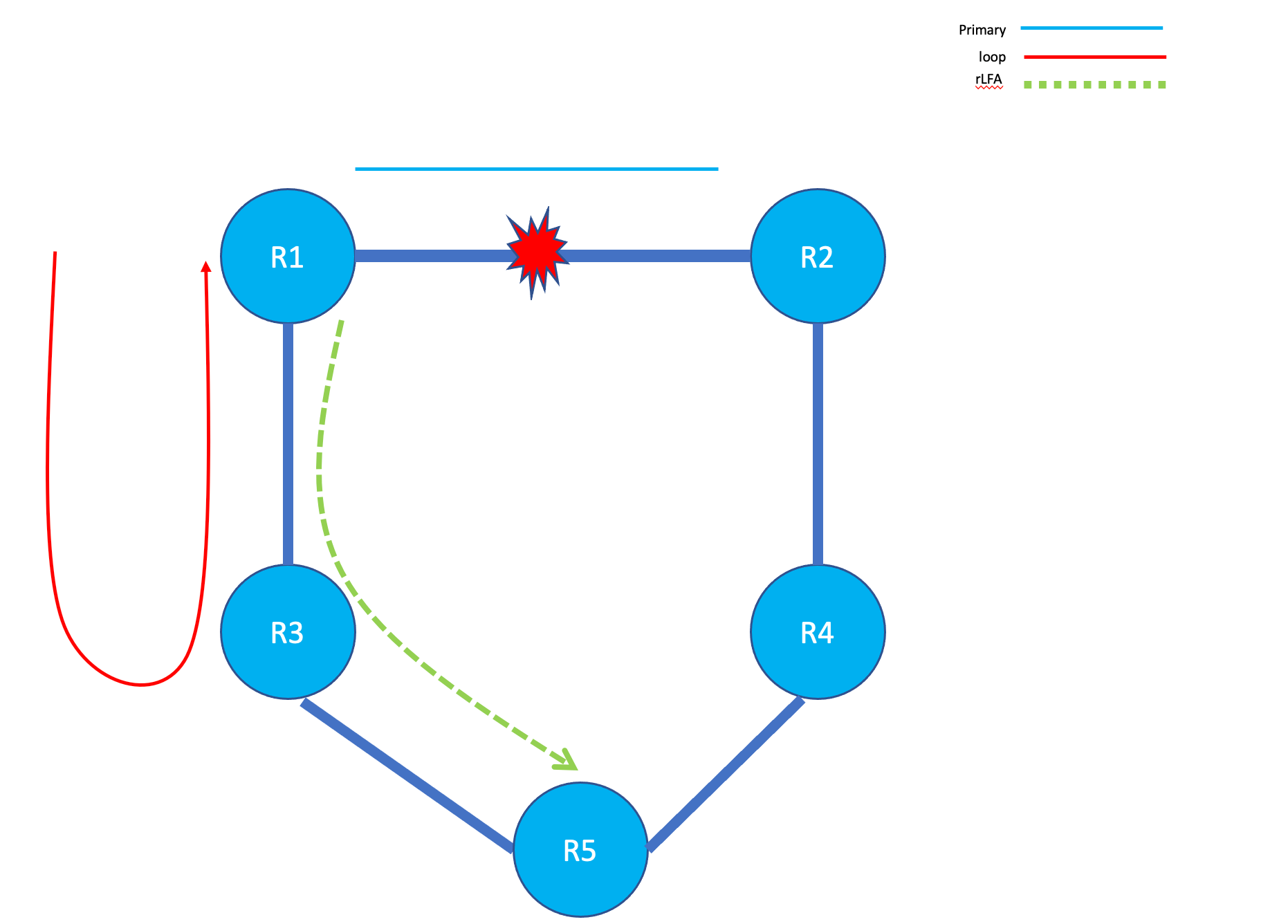
Now think of a situation where the primary link between R1 and R2 fails and R1 selects R3 as the backup path. Here R3 doesn’t know about the failure and hence have not converged its routing table yet. So R3 still thinks that R1 is the better router to reach to the prefixes residing on R2 hence looping the traffic back to R1 and creating loop until the convergence finally happens(see the below diag). We also call this microloop.
rLFA works along with MPLS on Cisco devices, so you need to have mpls up and running between all devices along the path. rLFA builds a tunnel from source(R1 in this case) and tail (R5 in this case) with the help of directed MPLS session between R1 and R5. The tunnel interface will look something like below:
MPLS-Remote-Lfa1 is up, line protocol is up
  Hardware is MPLS-Remote-Lfa
  Interface is unnumbered. Using address of GigabitEthernet2 (10.10.10.5)
  MTU 17892 bytes, BW 9 Kbit/sec, DLY 500000 usec,
     reliability 255/255, txload 1/255, rxload 1/255
  Encapsulation UNKNOWN, loopback not set
  Keepalive not set
  0x7F955CCA8898 (0x0) type LDP idb 0x7F95896E5FF8,13,MP1 out_if 0x7F95589224C0,8,Gi2 nh 10.10.10.6 topo 0x0 tail 7.7.7.7 specific lbl=24007, flags=0x200 adj=0x7F955D6A2FB8(IP),0x0(),0x7F955D6A2D88(TAG), path_spec=I/F=0x7F95589224C0,8,Gi2 nh=10.10.10.6 pfx=7.7.7.7/32 topo/ctx_id=0x0/0 nh_ctx=0 lbl=1048577 client=10
  Last input never, output never, output hang never
  Last clearing of "show interface" counters never
  Input queue: 0/375/0/0 (size/max/drops/flushes); Total output drops: 0
  Queueing strategy: fifo
  Output queue: 0/0 (size/max)
  5 minute input rate 0 bits/sec, 0 packets/sec
  5 minute output rate 0 bits/sec, 0 packets/sec
     0 packets input, 0 bytes, 0 no buffer
     Received 0 broadcasts (0 IP multicasts)
     0 runts, 0 giants, 0 throttles
     0 input errors, 0 CRC, 0 frame, 0 overrun, 0 ignored, 0 abort
     0 packets output, 0 bytes, 0 underruns
     Output 0 broadcasts (0 IP multicasts)
     0 output errors, 0 collisions, 0 interface resets
     0 unknown protocol drops
     0 output buffer failures, 0 output buffers swapped out

R1#sh mpls  ldp neighbor
    Peer LDP Ident: 5.5.5.5:0; Local LDP Ident 1.1.1.1:0
	TCP connection: 5.5.5.5.63962 - 1.1.1.1.646
	State: Oper; Msgs sent/rcvd: 62/65; Downstream
	Up time: 00:38:12
	LDP discovery sources:
	  GigabitEthernet2, Src IP addr: 10.10.10.6
        Addresses bound to peer LDP Ident:
          10.10.10.6      20.20.20.1      5.5.5.5
    Peer LDP Ident: 2.2.2.2:0; Local LDP Ident 1.1.1.1:0
	TCP connection: 2.2.2.2.50220 - 1.1.1.1.646
	State: Oper; Msgs sent/rcvd: 50/50; Downstream
	Up time: 00:28:03
	LDP discovery sources:
	  GigabitEthernet1, Src IP addr: 10.10.10.2
        Addresses bound to peer LDP Ident:
          2.2.2.2         10.10.10.2      10.10.10.9
    Peer LDP Ident: 7.7.7.7:0; Local LDP Ident 1.1.1.1:0
	TCP connection: 7.7.7.7.62386 - 1.1.1.1.646
	State: Oper; Msgs sent/rcvd: 46/47; Downstream
	Up time: 00:25:40
	LDP discovery sources:
	  Targeted Hello 1.1.1.1 -> 7.7.7.7, active, passive
        Addresses bound to peer LDP Ident:
          10.10.10.18     20.20.20.6      7.7.7.7
    Peer LDP Ident: 3.3.3.3:0; Local LDP Ident 1.1.1.1:0
	TCP connection: 3.3.3.3.36284 - 1.1.1.1.646
	State: Oper; Msgs sent/rcvd: 46/47; Downstream
	Up time: 00:25:40
	LDP discovery sources:
	  Targeted Hello 1.1.1.1 -> 3.3.3.3, active, passive
        Addresses bound to peer LDP Ident:
          3.3.3.3         10.10.10.13     10.10.10.17
Above outputs give us great deal of information about the tunnel path. For example the tunnel is unnumbered tunnel using G2 interface’s IP address. The next hop ip address for the tunnel, and the tail of the tunnel. This is the path which will be followed when the primary path fails.
Also you can clearly see in mpls ldp neighborship that the targeted LDP sessions were auto created with the tail ends. These targeted LDP sessions are crucial to build the path. You can
NOTE : Please do not try to match the outputs with the below diag, network diag and the outputs are not from same topology.
You can also see rLFA tunnels with following commands.
R1#sh isis fast-reroute remote-lfa tunnels

Tag CORE - Fast-Reroute Remote-LFA Tunnels:

  MPLS-Remote-Lfa1: use Gi2, nexthop 10.10.10.6, end point 7.7.7.7
  MPLS-Remote-Lfa2: use Gi1, nexthop 10.10.10.2, end point 3.3.3.3
rLFA configuration :
Now finally lets see the configurations on IOS-XE and IOS-XR devices.
IOS-XE Router:

!
router isis CORE
 net 49.0000.0000.0001.00
 is-type level-1
 fast-reroute per-prefix level-1 all
 fast-reroute remote-lfa level-1 mpls-ldp
!


IOS-XR Router:

!
router isis CORE
 is-type level-1
 net 49.0000.0000.0005.00
 address-family ipv4 unicast
 !
 address-family ipv6 unicast
  single-topology
 !
 interface Loopback1
  address-family ipv4 unicast
  !
  address-family ipv6 unicast
  !
 !
 interface GigabitEthernet0/0/0/0
  circuit-type level-1
  point-to-point
  address-family ipv4 unicast
   fast-reroute per-prefix
   fast-reroute per-prefix remote-lfa tunnel mpls-ldp
!


NOTE : Make sure to have MPLS running along the path else the rLFA tunnels wont come up.
Here you can see that we need to mention in configuration that we are going to use mpls-ldp to create tunnels.
Conclusion :
I will conclude this blog for now. The intention was to provide you an overall picture related to FRR and it’s usage. With this you can start working on FRR and gain experience. In my upcoming blogs I will try to dwell into some further details of FRR like usage of BFD , FRR coverage and rLFA conditions (like feasibility condition in EIGRP) etc. So stay tuned and happy learning!!