This is the second blog in segment routing series. Please check other segment routing blogs here:
GNS3 LAB: Segment Routing Configuration on Cisco IOS-XE and IOS-XR routers.
In this blog I will discuss about the Segment routing based traffic engineering with the MPLS data plane. You already know that in order to run MPLS traffic engineering we need to enable RSVP end to end which helps in label distribution and signalling.But in segment routing the label distribution part is taken care by IGP (ISIS TLVs or OSPF opaque LSA) in MPLS data plane and in IPv6 extension headers in case of SRv6. In this blog I will cover MPLS data plane using ISIS as the IGP.
In Segment routing traffic engineering we use source routing which means that TE headend will know the end to end path which it will put on the packet as label stack while sending packets out. something like below examples…
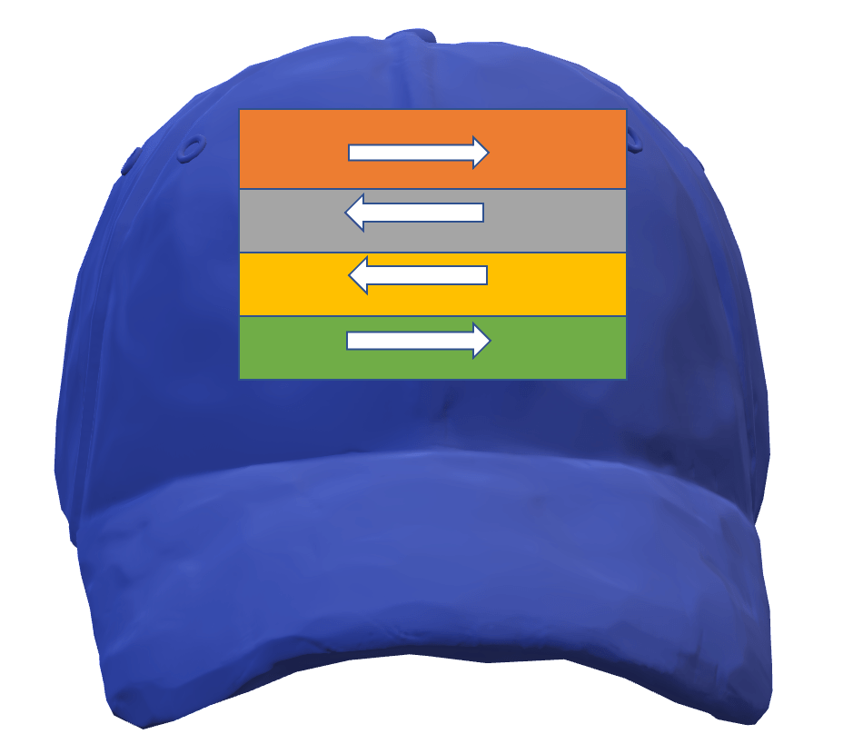
Juniper’s Ron Bonica’s example:
I found this example over the internet, where Ron talks about a kindergarten kid who needs to go to his home and he doesn’t know the path. At every road intersection, we have a guard who can help the kid. But the kid needs to carry the path info and it is done with the help of sticking labels on the kid’s cap. The kid has a cap with the labels which indicate direction something like below and now the guard needs to read the label and pop it and send the kid to the label indicated direction.
In this example, the best part is that the guard doesn’t need to remember the path for each kid.
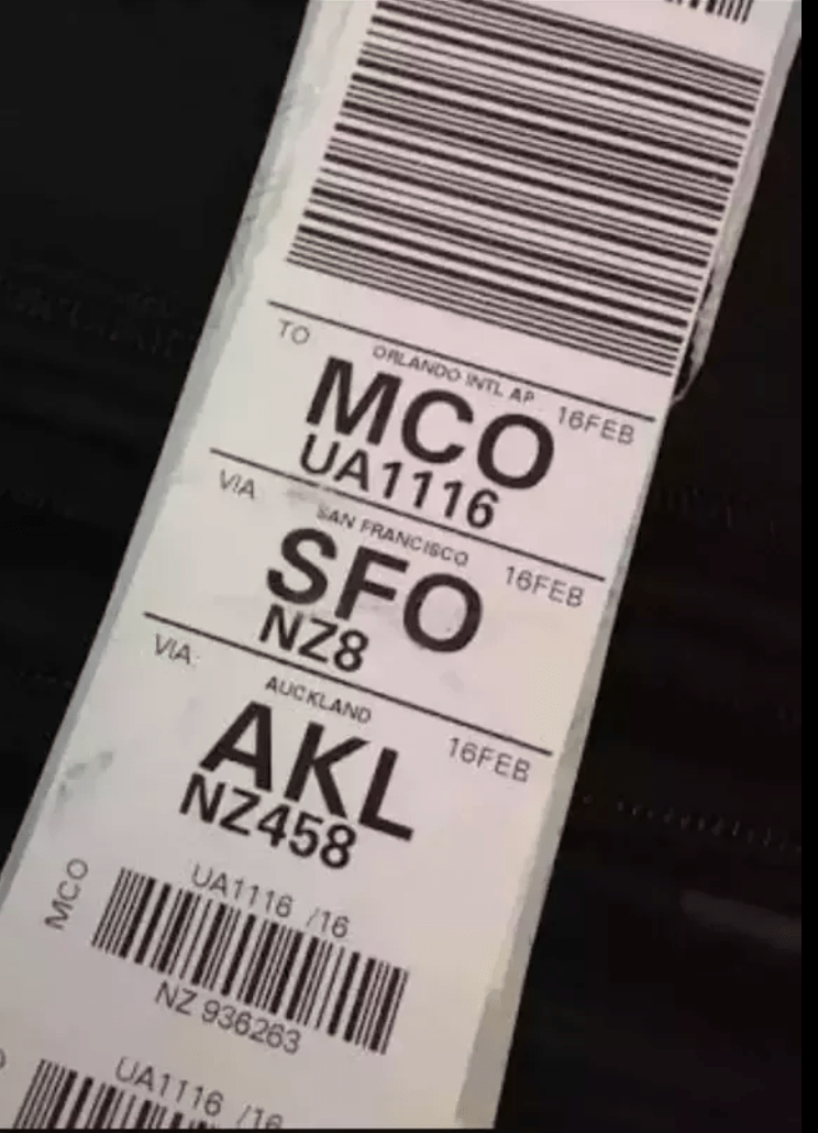
Cisco’s baggage transfer example :
Baggage tags generally hold the complete route info and are placed on the bags at the beginning of the trip. By this, every transit airport knows where to send the baggage next.
The above two examples give an excellent clue on how the traffic is steered over the segment routing path in MPLS TE.
Configuration:
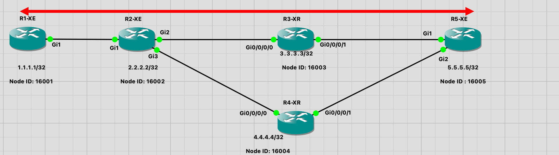
Before the configuration lets see the network diag.
Check the below diag, here I have configured TE tunnels between R1-XE router with R5-XE.
Before we begin I assume that you will check my previous segment routing blog for the basic configuration needed before we enable traffic engineering. GNS3 LAB: Segment Routing Configuration on Cisco IOS-XE and IOS-XR routers.
Basically below is what the configuration flow will look like.
- Configure link state IGP
- Enable segment routing
- Enable traffic engineering on each router and also core facing interfaces.
- Configure TE tunnels.
Note : On Cisco IOS-XE routers when ISIS is used as IGP we need to make the core facing interfaces point-to-point. As the traffic engineering is not supported over the broadcast interface.
R1-XE Config (Tunnel headend) :

!
mpls traffic-eng tunnels
!
interface GigabitEthernet1
 ip address 10.10.10.1 255.255.255.252
 ip router isis LAB
 mpls traffic-eng tunnels
 isis circuit-type level-1
 isis network point-to-point
!
router isis LAB
 net 49.0000.0000.0000.0001.00
 is-type level-1
 metric-style wide
 segment-routing mpls
 mpls traffic-eng router-id Loopback1
 mpls traffic-eng level-1
!
segment-routing mpls
 !
 connected-prefix-sid-map
  address-family ipv4
   1.1.1.1/32 index 1 range 1
  exit-address-family
 !
interface Tunnel1
 ip unnumbered Loopback1
 tunnel mode mpls traffic-eng
 tunnel destination 5.5.5.5
 tunnel mpls traffic-eng autoroute announce
 tunnel mpls traffic-eng priority 6 6
 tunnel mpls traffic-eng path-option 10 explicit name SR-PATH segment-routing
!
ip explicit-path name SR-PATH enable
 index 1 next-label 16002
 index 2 next-label 16004
 index 3 next-label 16005
!


R5-XE configuration(Tunnel Tail end):

!
mpls traffic-eng tunnels
!
interface GigabitEthernet1
 ip address 10.10.10.14 255.255.255.252
 ip router isis LAB
 mpls traffic-eng tunnels
 isis circuit-type level-1
 isis network point-to-point
!
!
interface GigabitEthernet2
 ip address 10.10.10.18 255.255.255.252
 ip router isis LAB
 mpls traffic-eng tunnels
 isis circuit-type level-1
 isis network point-to-point
!
router isis LAB
 net 49.0000.0000.0000.0005.00
 is-type level-1
 metric-style wide
 segment-routing mpls
 mpls traffic-eng router-id Loopback1
 mpls traffic-eng level-1
!
segment-routing mpls
 !
 connected-prefix-sid-map
  address-family ipv4
   5.5.5.5/32 index 5 range 1
  exit-address-family
 !
!
interface Tunnel1
 ip unnumbered Loopback1
 tunnel mode mpls traffic-eng
 tunnel destination 1.1.1.1
 tunnel mpls traffic-eng autoroute announce
 tunnel mpls traffic-eng priority 6 6
 tunnel mpls traffic-eng path-option 10 explicit name SR-PATH segment-routing
!
ip explicit-path name SR-PATH enable
 index 1 next-label 16004
 index 2 next-label 16002
 index 3 next-label 16001
!
Verification
For verification purpose I have configured a loopback on both of these routers. I am routing these loopbacks traffic over the tunnel with the help of static route. Check out the config below…
R1-XE:

!
interface Loopback2
 ip address 192.168.10.1 255.255.255.255
!
ip route 192.168.20.1 255.255.255.255 Tunnel1

R5-XE:

!
interface Loopback2
 ip address 192.168.20.1 255.255.255.255
!
ip route 192.168.10.1 255.255.255.255 Tunnel1
!
Lets check if ping and traces are working. Notice two labels in traceroute, 16004 and 16005 which is inserted at the beginning of the network.
R1-XE#ping 192.168.20.1
Type escape sequence to abort.
Sending 5, 100-byte ICMP Echos to 192.168.20.1, timeout is 2 seconds:
!!!!!
Success rate is 100 percent (5/5), round-trip min/avg/max = 1/2/3 ms

R1-XE#traceroute 192.168.20.1
Type escape sequence to abort.
Tracing the route to 192.168.20.1
VRF info: (vrf in name/id, vrf out name/id)
  1 10.10.10.2 [MPLS: Labels 16004/16005 Exp 0] 2 msec 2 msec 2 msec
  2 10.10.10.10 [MPLS: Label 16005 Exp 0] 1 msec 3 msec 2 msec
  3 10.10.10.18 2 msec *  4 msec

R1-XE#sh mpls traffic-eng tunnels tun 1

Name: R1-XE_t1                            (Tunnel1) Destination: 5.5.5.5
  Status:
    Admin: up         Oper: up     Path: valid       Signalling: connected
    path option 10, (SEGMENT-ROUTING) type explicit SR-PATH (Basis for Setup)

  Config Parameters:
    Bandwidth: 0        kbps (Global)  Priority: 6  6   Affinity: 0x0/0xFFFF
    Metric Type: TE (default)
    Path Selection:
     Protection: any (default)
    Path-selection Tiebreaker:
      Global: not set   Tunnel Specific: not set   Effective: min-fill (default)
    Hop Limit: disabled [ignore: Explicit Path Option with all Strict Hops]
    Cost Limit: disabled
    Path-invalidation timeout: 10000 msec (default), Action: Tear
    AutoRoute: enabled  LockDown: disabled Loadshare: 0 [0] bw-based
    auto-bw: disabled
    Fault-OAM: disabled, Wrap-Protection: disabled, Wrap-Capable: No
  Active Path Option Parameters:
    State: explicit path option 10 is active
    BandwidthOverride: disabled  LockDown: disabled  Verbatim: disabled

  History:
    Tunnel:
      Time since created: 24 minutes
      Time since path change: 22 minutes, 34 seconds
      Number of LSP IDs (Tun_Instances) used: 16
    Current LSP: [ID: 16]
      Uptime: 22 minutes, 34 seconds
  Tun_Instance: 16
  Segment-Routing Path Info (isis  level-1)
    Segment0[Node]: 2.2.2.2, Label: 16002
    Segment1[Node]: 4.4.4.4, Label: 16004
    Segment2[Node]: 5.5.5.5, Label: 16005
R1-XE#
Conclusion :
So much is remaining to discuss for SRTE, my next blog will discuss SRTE configurations on IOS-XR with the help of segment routing polices. On top of that, TE discussion is not complete if we don’t discuss ti-LFA. Stay tuned keep reading. Thanks.