This blog is very close to my heart because this is the first one where the lab is done on my recently built remote GNS3 server. Please check my blog on how to configure GNS3 as a remote server here How to Run GNS3 in Client Server Mode
Now, lets get started with Segment routing. Before getting into the configuration I really wanted to discuss few major points we should know about segment routing and how those are bringing change in the world on layer-2 forwarding.
- Segment routing is seen as an evolution of our old MPLS and MPLS-TE based label forwarding.
- In comparison with the above two technologies, it brings so much on the table but most importantly with segment routing we don’t need a protocol to generate or distribute labels like LDP or RSVP.
- Segment routing uses capabilities of Link state routing protocols like TLVs in ISIS and Opaque LSA in OSPF to pass the label and other information in MPLS data-plane based SR.
- In IPv6 data-plane based SR or SRv6 it uses the fields in IPv6 itself to pass the same information.
- SRv6 is further extended to another version SRv6+ where the extension headers are compressed because IPv6 headers were becoming huge.
- Now, we can see that how nicely we have eliminated LDP and RSVP, Link state routing protocols and IPv6 is turning into a Swiss army knife for the networking world.
- In case of MPLS-TE segment routing uses source routing where the source knows about the complete path and while sending packet out it just embeds that path in the packet. Now the intermediate nodes just have to remove(pop) the labels belonging to them and steer the packet to the node where the next label belongs to.
- As we are using links state routing protocols, we can use IGP FRR in segment routing.
- There are two important components in SR, Prefix-SID and Adjacency SID, with the help of these two we can reach anywhere in the network.
- On each router we mention an index value which is carried in the IGP advertisement and the receiving end calculates the label based on index value it has received from the node.It is done on the basis of SRGB (segment routing global block) defined on the router, for example if the SRGB defined on the router is 16000 to 23999 which is also the default SRGB and router receives 5 as index value then the label would be 16005.
- The prefix sid steers the traffic to the right node and the adj sid steers the traffic to the right adjacency to reach that node.
- Also the best part is the SDN controller based control plane.
I think I have listed enough here, now let’s get into two very good analogies that I found over the internet and they really helped me to understand the SR operation when TE is configured over SR.
Juniper ‘s Ron Bonica’s example:
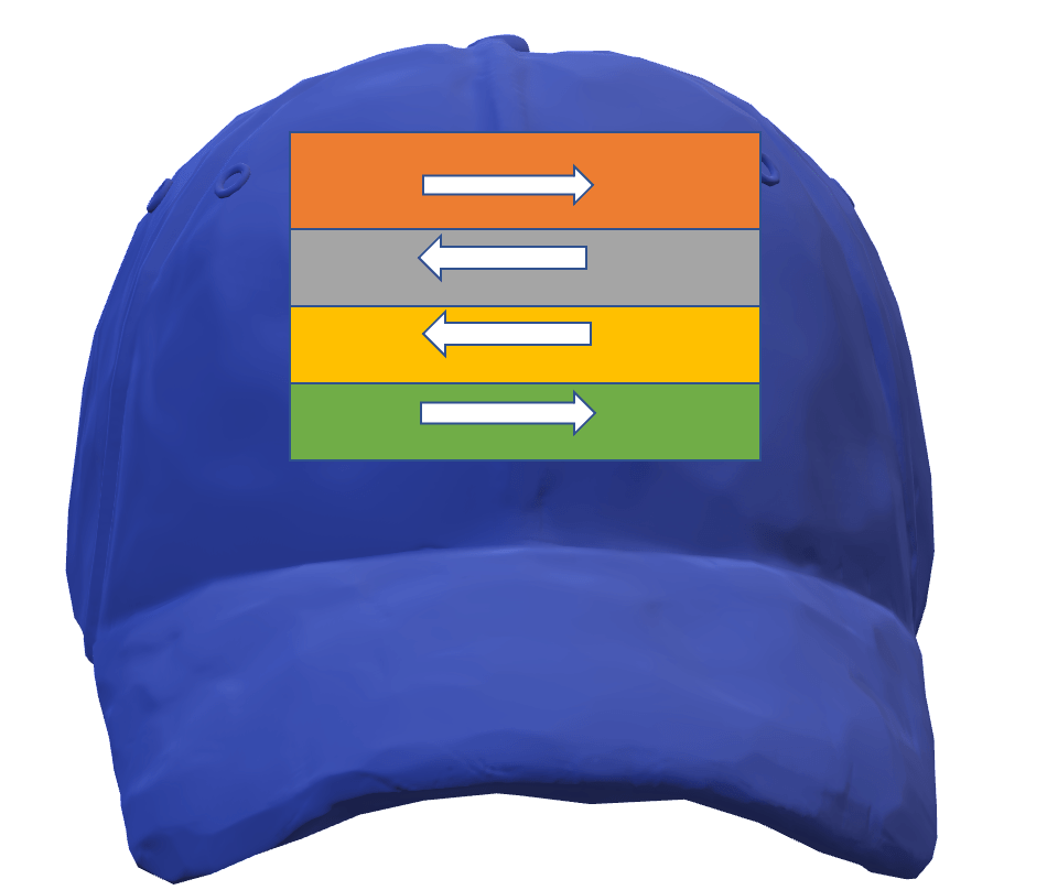
I found this example over the internet, where Ron talks about a kindergarten kid who needs to go to his home and he doesn’t know the path. At every road intersection, we have a guard who can help the kid. But the kid needs to carry the path info and it is done with the help of sticking labels on the kid’s cap. The kid has a cap with the labels which indicate direction something like below and now the guard needs to read the label and pop it and send the kid to the label indicated direction.
In this example, the best part is that the guard doesn’t need to remember the path for each kid.
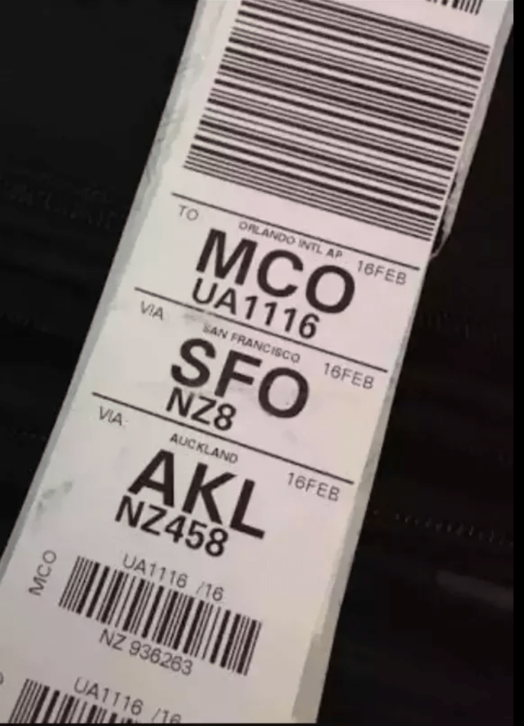
Cisco’s baggage transfer example :
Baggage tags generally hold the complete route info and are placed on the bags at the beginning of the trip. By this, every transit airport knows where to send the baggage next.
The above two examples give an excellent clue on how the traffic is steered over the segment routing path in MPLS TE.
Configurations :
I am using the below topology for the segment routing configuration, I will talk about basic segment routing configuration and will not add TE(traffic engineering) for now, for TE will come in the next blog.

I have CSR1000v Running 17.3.2 and IOS-XRv router running 7.1.1. release. Lets see the configurations.
IOS-XE configuration :
hostname R1-XE
!
interface Loopback1
 ip address 1.1.1.1 255.255.255.255
 ip router isis LAB
!
interface GigabitEthernet1
 ip address 10.10.10.1 255.255.255.252
 ip router isis LAB
 negotiation auto
 no mop enabled
 no mop sysid
 isis circuit-type level-1
 isis network point-to-point
!
segment-routing mpls
 !
 connected-prefix-sid-map
  address-family ipv4
   1.1.1.1/32 index 1 range 1
  exit-address-family
 !
!
router isis LAB
 net 49.0000.0000.0000.0001.00
 is-type level-1
 metric-style wide
 segment-routing mpls
!
IOS-XR Configuration :
!
hostname R3-XR
!
interface Loopback1
 ipv4 address 3.3.3.3 255.255.255.255
!
interface MgmtEth0/0/CPU0/0
 shutdown
!
interface GigabitEthernet0/0/0/0
 ipv4 address 10.10.10.6 255.255.255.252
!
interface GigabitEthernet0/0/0/1
 ipv4 address 10.10.10.13 255.255.255.252
!
router isis LAB
 is-type level-1
 net 49.0000.0000.0000.0003.00
 address-family ipv4 unicast
  metric-style wide
  segment-routing mpls
 !
 interface Loopback1
  address-family ipv4 unicast
   prefix-sid index 3
  !
 !
 interface GigabitEthernet0/0/0/0
  circuit-type level-1
  point-to-point
  address-family ipv4 unicast
  !
 !
 interface GigabitEthernet0/0/0/1
  circuit-type level-1
  point-to-point
  address-family ipv4 unicast
  !
 !
!
end
Verification
Notice the traceroute in below output, all hops assign the same label, this is different than our old hop-by-hop label swap method. Here the swap happens but the label remains same.
On XE Router :

R1-XE#sh mpls forwarding-table
Local      Outgoing   Prefix           Bytes Label   Outgoing   Next Hop
Label      Label      or Tunnel Id     Switched      interface
16         Pop Label  10.10.10.2-A     0             Gi1        10.10.10.2
17         Pop Label  10.10.10.2-A     0             Gi1        10.10.10.2
16002      Pop Label  2.2.2.2/32       0             Gi1        10.10.10.2
16003      16003      3.3.3.3/32       0             Gi1        10.10.10.2
16004      16004      4.4.4.4/32       0             Gi1        10.10.10.2
16005      16005      5.5.5.5/32       0             Gi1        10.10.10.2

R1-XE#sh segment-routing mpls connected-prefix-sid-map ipv4

               PREFIX_SID_CONN_MAP ALGO_0

    Prefix/masklen   SID Type Range Flags SRGB
        1.1.1.1/32     1 Indx     1         Y

               PREFIX_SID_PROTOCOL_ADV_MAP ALGO_0

    Prefix/masklen   SID Type Range Flags SRGB Source
        1.1.1.1/32     1 Indx     1         Y  IS-IS Level 1 0000.0000.0001
        2.2.2.2/32     2 Indx     1         Y  IS-IS Level 1 0000.0000.0002
        3.3.3.3/32     3 Indx     1         Y  IS-IS Level 1 0000.0000.0003
        4.4.4.4/32     4 Indx     1         Y  IS-IS Level 1 0000.0000.0004
        5.5.5.5/32     5 Indx     1         Y  IS-IS Level 1 0000.0000.0005


R1-XE#traceroute 5.5.5.5
Type escape sequence to abort.
Tracing the route to 5.5.5.5
VRF info: (vrf in name/id, vrf out name/id)
  1 10.10.10.2 [MPLS: Label 16005 Exp 0] 33 msec 2 msec 2 msec
  2 10.10.10.6 [MPLS: Label 16005 Exp 0] 3 msec 1 msec 1 msec
  3 10.10.10.14 101 msec *  2 msec

On XR router

RP/0/0/CPU0:R3-XR#sh mpls forwarding
Wed Jul 28 04:33:38.962 UTC
Local  Outgoing    Prefix             Outgoing     Next Hop        Bytes
Label  Label       or ID              Interface                    Switched
------ ----------- ------------------ ------------ --------------- ------------
16001  16001       SR Pfx (idx 1)     Gi0/0/0/0    10.10.10.5      0
       16004       SR Pfx (idx 1)     Gi0/0/0/1    10.10.10.14     0            (!)
16002  Pop         SR Pfx (idx 2)     Gi0/0/0/0    10.10.10.5      0
       16004       SR Pfx (idx 2)     Gi0/0/0/1    10.10.10.14     0            (!)
16004  16004       SR Pfx (idx 4)     Gi0/0/0/0    10.10.10.5      0
       16004       SR Pfx (idx 4)     Gi0/0/0/1    10.10.10.14     0
16005  Pop         SR Pfx (idx 5)     Gi0/0/0/1    10.10.10.14     0
       16004       SR Pfx (idx 5)     Gi0/0/0/0    10.10.10.5      0            (!)
24000  Pop         SR Adj (idx 0)     Gi0/0/0/0    10.10.10.5      0
       16004       SR Adj (idx 0)     Gi0/0/0/1    10.10.10.14     0            (!)
24001  Pop         SR Adj (idx 2)     Gi0/0/0/0    10.10.10.5      0
24002  Pop         SR Adj (idx 0)     Gi0/0/0/1    10.10.10.14     0
       16004       SR Adj (idx 0)     Gi0/0/0/0    10.10.10.5      0            (!)
24003  Pop         SR Adj (idx 2)     Gi0/0/0/1    10.10.10.14     0


RP/0/0/CPU0:R3-XR#sh mpls forwarding prefix 1.1.1.1/32
Wed Jul 28 04:33:56.671 UTC
Local  Outgoing    Prefix             Outgoing     Next Hop        Bytes
Label  Label       or ID              Interface                    Switched
------ ----------- ------------------ ------------ --------------- ------------
16001  16001       SR Pfx (idx 1)     Gi0/0/0/0    10.10.10.5      0
       16004       SR Pfx (idx 1)     Gi0/0/0/1    10.10.10.14     0            (!)
Wireshark Nirvana!!!
No matter whatever clarity I have in the technology I always look for Wireshark capture as it helps me in tech nirvana. I don’t want to see much after seeing the packet 😀 😀
In this capture, let’s see how index values are transferred between the segment router running routers. The below screenshot is of LSP received on R1-XE router from R2-XE router which is telling its index value in TLV 135.

Conclusion:
This blog was just the start, I am going to discuss more on SR as there is a huge world of SR out there. My next blog will be on MPLS traffic engineering configuration and then I will also cover SRv6. At the end I will have a lab with Cisco NSO and GNS3. Thanks for your time and stay tuned for more!!
Dont forget to check related blogs:
GNS3 LAB Cisco : Segment Routing traffic engineering configuration on IOS-XE routers.
I have also created a basic video on MPLS vs Segment routing please check it on my YouTube channel. Also please subscribe to the channel for more content like this.