So far we have seen EVPN single home and EVPN multihome setup and configuration with Cisco csr1000v router. You can find the links for those posts below.
EVPN -Single home GNS3 LAB Cisco : BGP-EVPN Single Home Configuration
EVPN -Multi homeGNS3 Lab Cisco : EVPN Multihome Concept and Configurations
Note : As per Cisco docs below EVPN IRB configuration is supported only on ASR 1000 device , I did the same on CSR1000v and found it working. On other cisco devices like XR and NXOS it is supported. So before implementing this config in your production please check with cisco about the support matrix.
What is IRB?
In my previous posts I have discussed communication within the same VLANs/Bridge-domain over the MPLS/IP network because that is the major correlation between the previous l2 extension over MPLS technologies like xconnect,vpls etc and the EVPN. However evpn goes further and facilitates the communication between the different subnets as well, like we used to do in l3vpn. So you can think evpn as a single package delivering l2vpn and l3vpn services.
Check my l2vpn and l3vpn posts here:
L2VPN : Cisco MPLS L2VPN (xConnect) GNS3 Configuration Example and Explanation
L3VPN : Cisco MPLS VPN(L3VPN) GNS3 Configuration Example and Explanation. Lab available for download.
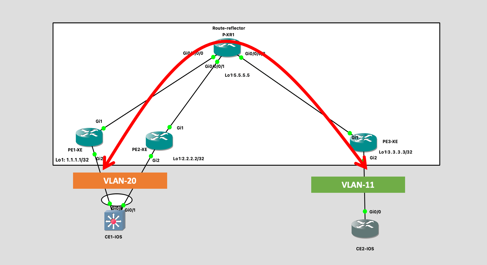
Network topology
For IRB I am going to follow below network diag.
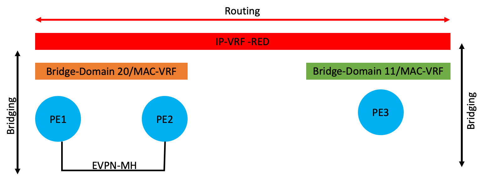
How does it work ?
There are two methods to do IRB, Symmetric config and Asymmetric config. Cisco has implemented symmetric IRB on its devices and I am going to discuss the same here. In symmetric IRB configuration we need to configure IRB interfaces (BDI interface) and attach it to the vrf on all PEs where the hosts belonging to the BD are located. For example in above topology, I will have to create BDI-20 on PE1 and PE2 router and BDI-11 on PE3. The IP addresses assigned on the BDI interface acts as a default gateway, in EVPN terms we also call it as DAG (Distributed anycast gateway). This is because on all PEs (leafs) we need to keep the IP address same for the BDI interfaces for a particular BD, for example in above topology if I need to create a BDI 20 on PE3 as well then the IP and mac address configured on PE1 and PE2 for BDI20 will be identically configured on PE3 as well. This is done to provide mobility of hosts which needs a consistent gateway IP address. Like in case of anycast we choose the nearest RP(PIM sparse mode) to forward traffic here also the nearest gateway will be chosen to forward traffic which is destined for the other subnets. Following is the logical dig of the operation.
Configuration
!
hostname PE1-XE
!
vrf definition red
 rd 100:1
 route-target export 100:100
 route-target import 100:100
 !
 address-family ipv4
  route-target export 100:100
  route-target import 100:100
  route-target export 100:100 stitching
  route-target import 100:100 stitching
 exit-address-family
!
mpls label protocol ldp
multilink bundle-name authenticated
l2vpn evpn
 replication-type ingress
 mpls label mode per-ce
 router-id Loopback1
!
l2vpn evpn instance 10 vlan-based
!
bridge-domain 10
 member Port-channel1 service-instance 10
 member evpn-instance 10
!
!
interface Loopback1
 ip address 1.1.1.1 255.255.255.255
!
interface Port-channel1
 evpn ethernet-segment 1
  identifier type 3 system-mac abcd.abcd.abcd
  redundancy all-active
 service instance 10 ethernet
  encapsulation dot1q 20
  rewrite ingress tag pop 1 symmetric
 !
 service instance 11 ethernet
  encapsulation dot1q 11
  rewrite ingress tag pop 1 symmetric
 !
!
interface GigabitEthernet1
 ip address 10.10.10.1 255.255.255.252
 mpls ip
!
interface GigabitEthernet2
 channel-group 1
!
interface BDI10
 mac-address 0011.0011.0010
 vrf forwarding red
 ip address 20.20.20.11 255.255.255.0
!
router ospf 1
 router-id 1.1.1.1
 network 0.0.0.0 255.255.255.255 area 0
!
router bgp 100
 bgp router-id 1.1.1.1
 bgp log-neighbor-changes
 neighbor 5.5.5.5 remote-as 100
 neighbor 5.5.5.5 update-source Loopback1
 !
 address-family ipv4
  neighbor 5.5.5.5 activate
 exit-address-family
 !
 address-family l2vpn evpn
  neighbor 5.5.5.5 activate
  neighbor 5.5.5.5 send-community both
  neighbor 5.5.5.5 soft-reconfiguration inbound
 exit-address-family
 !
 address-family ipv4 vrf red
  advertise l2vpn evpn
  bgp additional-paths install
  redistribute connected
  maximum-paths ibgp 10
 exit-address-family
!
hostname PE2-XE
!
vrf definition red
 rd 100:1
 !
 address-family ipv4
  route-target export 100:100
  route-target import 100:100
  route-target export 100:100 stitching
  route-target import 100:100 stitching
 exit-address-family
!
mpls label protocol ldp
multilink bundle-name authenticated
l2vpn evpn
 replication-type ingress
 mpls label mode per-ce
 router-id Loopback1
!
l2vpn evpn instance 10 vlan-based
!
bridge-domain 10
 member Port-channel1 service-instance 10
 member evpn-instance 10
!
!
interface Loopback1
 ip address 2.2.2.2 255.255.255.255
!
interface Port-channel1
 no ip address
 no negotiation auto
 no mop enabled
 no mop sysid
 evpn ethernet-segment 1
  identifier type 3 system-mac abcd.abcd.abcd
  redundancy all-active
 service instance 10 ethernet
  encapsulation dot1q 20
  rewrite ingress tag pop 1 symmetric
 !
 service instance 11 ethernet
  encapsulation dot1q 11
  rewrite ingress tag pop 1 symmetric
 !
!
interface GigabitEthernet1
 ip address 10.10.10.5 255.255.255.252
 mpls ip
!
interface GigabitEthernet2
 channel-group 1
!
interface BDI10
 mac-address 0011.0011.0010
 vrf forwarding red
 ip address 20.20.20.11 255.255.255.0
!
router ospf 1
 router-id 2.2.2.2
 network 0.0.0.0 255.255.255.255 area 0
!
router bgp 100
 bgp router-id 2.2.2.2
 bgp log-neighbor-changes
 neighbor 5.5.5.5 remote-as 100
 neighbor 5.5.5.5 update-source Loopback1
 !
 address-family ipv4
  neighbor 5.5.5.5 activate
 exit-address-family
 !
 address-family l2vpn evpn
  neighbor 5.5.5.5 activate
  neighbor 5.5.5.5 send-community both
  neighbor 5.5.5.5 soft-reconfiguration inbound
 exit-address-family
 !
 address-family ipv4 vrf red
  advertise l2vpn evpn
  bgp additional-paths install
  redistribute connected
  maximum-paths ibgp 10
 exit-address-family
!
!
hostname PE3-XE
!
boot-start-marker
boot-end-marker
!
!
vrf definition red
 rd 100:1
 !
 address-family ipv4
  route-target export 100:100
  route-target import 100:100
  route-target export 100:100 stitching
  route-target import 100:100 stitching
 exit-address-family
!
l2vpn evpn
 replication-type ingress
 mpls label mode per-ce
 router-id Loopback1
!
l2vpn evpn instance 11 vlan-based
!
bridge-domain 11
 member GigabitEthernet2 service-instance 11
 member evpn-instance 11
!
interface Loopback1
 ip address 3.3.3.3 255.255.255.255
!
interface GigabitEthernet1
 ip address 10.10.10.10 255.255.255.252
 mpls ip
!
interface GigabitEthernet2
 service instance 10 ethernet
  encapsulation dot1q 10
  rewrite ingress tag pop 1 symmetric
 !
 service instance 11 ethernet
  encapsulation dot1q 11
  rewrite ingress tag pop 1 symmetric
 !
!
interface BDI11
 mac-address 0011.0011.0011
 vrf forwarding red
 ip address 11.11.11.1 255.255.255.0
!
router ospf 1
 router-id 3.3.3.3
 network 0.0.0.0 255.255.255.255 area 0
!
router bgp 100
 bgp router-id 3.3.3.3
 bgp log-neighbor-changes
 neighbor 5.5.5.5 remote-as 100
 neighbor 5.5.5.5 update-source Loopback1
 !
 address-family ipv4
  neighbor 5.5.5.5 activate
 exit-address-family
 !
 address-family l2vpn evpn
  neighbor 5.5.5.5 activate
  neighbor 5.5.5.5 send-community both
  neighbor 5.5.5.5 soft-reconfiguration inbound
 exit-address-family
 !
 address-family ipv4 vrf red
  advertise l2vpn evpn
  bgp additional-paths install
  redistribute connected
  maximum-paths ibgp 10
 exit-address-family
!
Now just like we had in L3VPN, with this configuration we should see he BDI network prefix routes in the vrf routing table. Like below. Keep in mind that we dont have any vpnv4 address family enabled in this case still we are able to exchange routes between the PEs.
PE1-XE#sh ip route vrf red

      11.0.0.0/24 is subnetted, 1 subnets
B        11.11.11.0 [200/0] via 3.3.3.3, 04:03:29
      20.0.0.0/8 is variably subnetted, 2 subnets, 2 masks
C        20.20.20.0/24 is directly connected, BDI10
L        20.20.20.11/32 is directly connected, BDI10
PE1-XE#
Verification
For verification purpose I have IPs assigned to respective VLANs on CE1 and CE2 routers in below manner. In order to verify the connectivity, I am going to ping between CE1 20.20.20.1 to CE2’s 11.11.11.2 IP address
CE1#sh ip int bri | ex una
Vlan11                 11.11.11.11     YES NVRAM  up                    up
Vlan20                 20.20.20.1      YES NVRAM  up                    up

CE2-IOS#sh ip int brief | ex una
Interface                  IP-Address      OK? Method Status                Protocol
GigabitEthernet0/0.10      20.20.20.2      YES NVRAM  up                    up
GigabitEthernet0/0.11      11.11.11.2      YES NVRAM  up                    up

CE1#ping 11.11.11.2 source 20.20.20.1
Type escape sequence to abort.
Sending 5, 100-byte ICMP Echos to 11.11.11.2, timeout is 2 seconds:
Packet sent with a source address of 20.20.20.1
!!!!!
Success rate is 100 percent (5/5), round-trip min/avg/max = 1/2/3 ms


CE2-IOS#ping 20.20.20.1 source 11.11.11.2
Type escape sequence to abort.
Sending 5, 100-byte ICMP Echos to 20.20.20.1, timeout is 2 seconds:
Packet sent with a source address of 11.11.11.2
!!!!!
Success rate is 100 percent (5/5), round-trip min/avg/max = 1/1/2 ms
CE2-IOS#