Introduction:
This article is focused on multi-homed EVPN setup that I have prepared in below network topology. One of the biggest advantage with EVPN that we get is multi-homing with it. Earlier with VPLS we did not have multi-homing integrated with the protocol. With multi-homing we can have one CE connected to two PE router and this type of configuration may run in A-A(Active-Active) mode or Single active mode. For now on IOS-XE device on which I am going to do configurations, runs only Active-Active mode.
- Active-Active Mode : In this mode both the links coming from CE to PE will be involved in active data forwarding. And we can very well load balance over it in per flow manner.
- Single Active Mode : In this mode one link will be sitting as standby and will become active once the active link becomes non operational due to some failure.
After configuration we will discuss few concepts like DF (Designated forwarder) Election, BUM traffic handling and loop prevention etc.
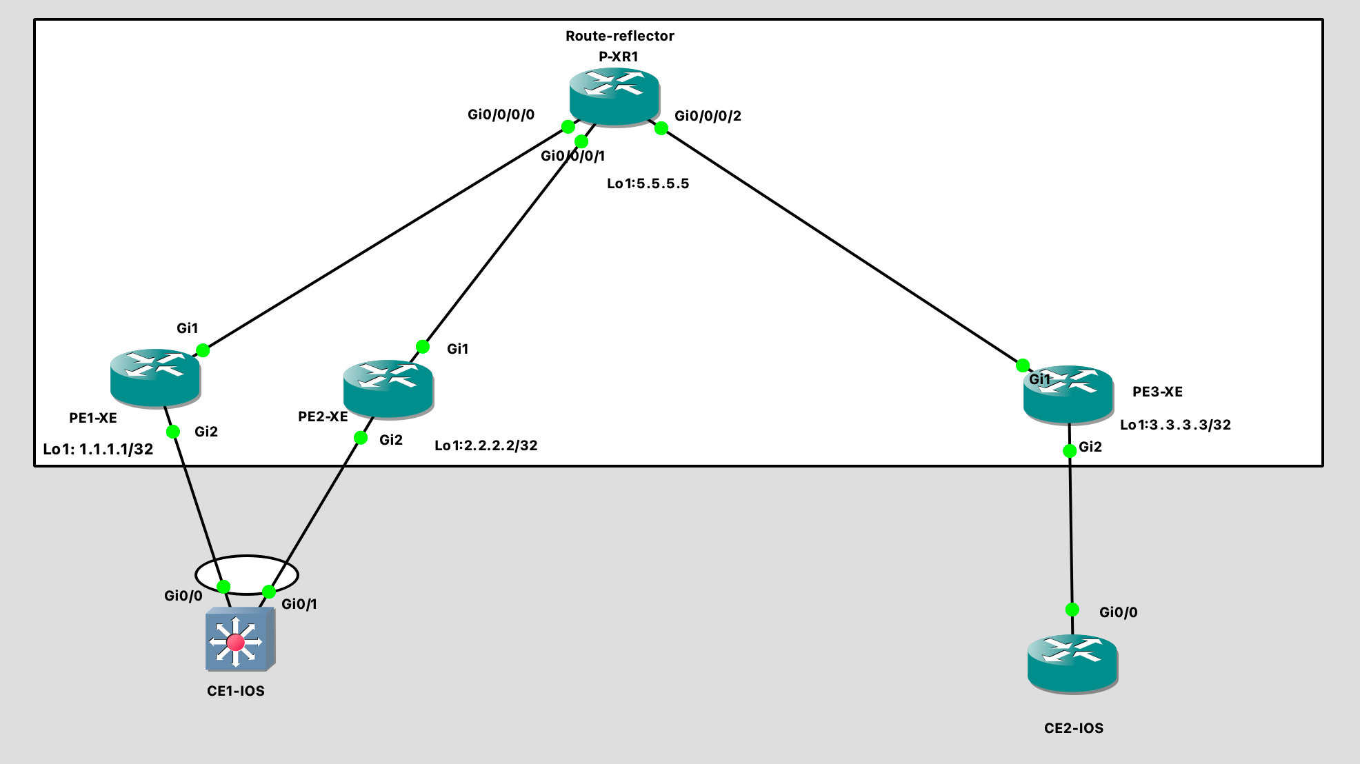
In the above topology the left CE (CE1-IOS) is configured for multihoming where PE1-XE and PE2-XE are serving as multihome gateway for the CE1-IOS. Lets quickly check the configuration.
Configuration:
PE1-XE Configuration:

!
hostname PE1-XE
!
l2vpn evpn
 replication-type ingress
 mpls label mode per-ce
 router-id Loopback1
!
l2vpn evpn instance 10 vlan-based
!
!
bridge-domain 10
 member Port-channel1 service-instance 10
 member evpn-instance 10
!
!
interface Loopback1
 ip address 1.1.1.1 255.255.255.255
!
interface Port-channel1
!
 evpn ethernet-segment 1
  identifier type 3 system-mac abcd.abcd.abcd
  redundancy all-active
 service instance 10 ethernet
  encapsulation untagged
 !
!
interface GigabitEthernet1
 ip address 10.10.10.1 255.255.255.252
 mpls ip
!
interface GigabitEthernet2
 channel-group 1
!
router ospf 1
 router-id 1.1.1.1
 network 0.0.0.0 255.255.255.255 area 0
!
router bgp 100
 bgp router-id 1.1.1.1
 bgp log-neighbor-changes
 neighbor 5.5.5.5 remote-as 100
 neighbor 5.5.5.5 update-source Loopback1
 !
 address-family ipv4
  neighbor 5.5.5.5 activate
 exit-address-family
 !
 address-family l2vpn evpn
  neighbor 5.5.5.5 activate
  neighbor 5.5.5.5 send-community both
  neighbor 5.5.5.5 soft-reconfiguration inbound
 exit-address-family
!
mpls ldp router-id Loopback1 force
!
Above is the configuration from PE1-XE, almost same mirror image configuration is needed on the other PE2-XE router as well. The common thing between the PE1-XE and PE2-XE is the portchannel, if you have seen vPC or VSS kind of setup this is similar to that. There is another common thing which is called Ethernet Segment in EVPN terms. An Ethernet segment attached to the CE device is common between the PE1-XE and PE2-XE and that is how it is seen by the rest of the network, means that the other end of the evpn, PE3-XE router will know that ethernet segment as a LAN which is reachable via both the PEs and hence can send the traffic back to any of these PEs. Lets check the configuration on other devices.
PE2-XE Config

!
hostname PE2-XE
!
l2vpn evpn
 replication-type ingress
 mpls label mode per-ce
 router-id Loopback1
!
l2vpn evpn instance 10 vlan-based
!
bridge-domain 10
 member Port-channel1 service-instance 10
 member evpn-instance 10
!
interface Loopback1
 ip address 2.2.2.2 255.255.255.255
!
interface Port-channel1
!
 evpn ethernet-segment 1
  identifier type 3 system-mac abcd.abcd.abcd
  redundancy all-active
 service instance 10 ethernet
  encapsulation untagged
 !
!
interface GigabitEthernet1
 ip address 10.10.10.5 255.255.255.252
 mpls ip
!
interface GigabitEthernet2
!
 channel-group 1
!
!
router ospf 1
 router-id 2.2.2.2
 network 0.0.0.0 255.255.255.255 area 0
!
router bgp 100
 bgp router-id 2.2.2.2
 bgp log-neighbor-changes
 neighbor 5.5.5.5 remote-as 100
 neighbor 5.5.5.5 update-source Loopback1
 !
 address-family ipv4
  neighbor 5.5.5.5 activate
 exit-address-family
 !
 address-family l2vpn evpn
  neighbor 5.5.5.5 activate
  neighbor 5.5.5.5 send-community both
  neighbor 5.5.5.5 soft-reconfiguration inbound
 exit-address-family
!
After we are done with the PE1-XE and PE2-XE configuration, let me share the configuration from PE3-XE, which is single home PE.You can find my single home blog here : GNS3 LAB Cisco : BGP-EVPN Single Home Configuration
PE3-XE Config
!
hostname PE3-XE
!
l2vpn evpn
 replication-type ingress
 mpls label mode per-ce
 router-id Loopback1
!
l2vpn evpn instance 10 vlan-based
!
!
bridge-domain 10
 member GigabitEthernet2 service-instance 10
 member evpn-instance 10
!
!
interface Loopback1
 ip address 3.3.3.3 255.255.255.255
!
interface GigabitEthernet1
 ip address 10.10.10.10 255.255.255.252
 negotiation auto
 mpls ip
!
interface GigabitEthernet2
 !
 service instance 10 ethernet
  encapsulation untagged
 !
!
!
router ospf 1
 router-id 3.3.3.3
 network 0.0.0.0 255.255.255.255 area 0
!
router bgp 100
 bgp router-id 3.3.3.3
 bgp log-neighbor-changes
 neighbor 5.5.5.5 remote-as 100
 neighbor 5.5.5.5 update-source Loopback1
 !
 address-family ipv4
  neighbor 5.5.5.5 activate
 exit-address-family
 !
 address-family l2vpn evpn
  neighbor 5.5.5.5 activate
  neighbor 5.5.5.5 send-community both
  neighbor 5.5.5.5 soft-reconfiguration inbound
 exit-address-family
!
Route-reflector configuration. This device is IOS-XR device.
P-XR1 Configuration:

!
hostname P-XR1
interface Loopback1
 ipv4 address 5.5.5.5 255.255.255.255
!
interface GigabitEthernet0/0/0/0
 ipv4 address 10.10.10.2 255.255.255.252
!
interface GigabitEthernet0/0/0/1
 ipv4 address 10.10.10.6 255.255.255.252
!
interface GigabitEthernet0/0/0/2
 ipv4 address 10.10.10.9 255.255.255.252
!
router ospf 1
 router-id 5.5.5.5
 area 0
  interface Loopback1
  !
  interface GigabitEthernet0/0/0/0
  !
  interface GigabitEthernet0/0/0/1
  !
  interface GigabitEthernet0/0/0/2
 !
!
router bgp 100
 address-family ipv4 unicast
 !
 address-family l2vpn evpn
 !
 neighbor 1.1.1.1
  remote-as 100
  update-source Loopback1
  address-family l2vpn evpn
   route-reflector-client
  !
 !
 neighbor 2.2.2.2
  remote-as 100
  update-source Loopback1
  address-family l2vpn evpn
   route-reflector-client
  !
 !
mpls ldp
 router-id 5.5.5.5
 interface GigabitEthernet0/0/0/0
 !
 interface GigabitEthernet0/0/0/1
 !
 interface GigabitEthernet0/0/0/2
 !
!
Thats it, this is all we need in ISP network , next we need to see the configuration of CE devices. Here the only CE connected to multihomed PE is CE1-IOS. The Major configuration that we need on CE is portchannel configuration. I have used port-channel mode “ON” here because that is the only mode supported by IOS-XE PEs.
The CE device which I am using here is a l3 switch.
CE1-IOS Configuration:

!
interface Port-channel10
 switchport access vlan 20
 switchport mode access
!
interface GigabitEthernet0/0
 switchport access vlan 20
 switchport mode access
 channel-group 10 mode on
!
interface GigabitEthernet0/1
 switchport access vlan 20
 switchport mode access
 channel-group 10 mode on
!
interface Vlan20
 ip address 20.20.20.1 255.255.255.0
!
Verification:
PE1-XE#show l2vpn evpn evi detail
EVPN instance:       10 (VLAN Based)
  RD:                1.1.1.1:10 (auto)
  Import-RTs:        100:10
  Export-RTs:        100:10
  Per-EVI Label:     none
  State:             Established
  Replication Type:  Ingress (global)
  Encapsulation:     mpls
  Bridge Domain:     10
    Ethernet-Tag:    0
    BUM Label:       17
    Per-BD Label:    none
    State:           Established
    Access If:
    Pseudoports (Labels):
      Port-channel1 service instance 10 (16) (DF state: forwarding)
        Routes: 0 MAC, 0 MAC/IP
    Peers:
      2.2.2.2
        Routes: 0 MAC, 0 MAC/IP, 1 IMET, 1 EAD
      3.3.3.3
        Routes: 1 MAC, 0 MAC/IP, 1 IMET, 0 EAD


PE2-XE#show l2vpn evpn evi detail
PE2-XE#sh l2vpn evpn evi detail
EVPN instance:       10 (VLAN Based)
  RD:                2.2.2.2:10 (auto)
  Import-RTs:        100:10
  Export-RTs:        100:10
  Per-EVI Label:     none
  State:             Established
  Replication Type:  Ingress (global)
  Encapsulation:     mpls
  Bridge Domain:     10
    Ethernet-Tag:    0
    BUM Label:       16
    Per-BD Label:    none
    State:           Established
    Access If:
    Pseudoports (Labels):
      Port-channel1 service instance 10 (23) (DF state: PE-to-CE BUM blocked)
        Routes: 0 MAC, 0 MAC/IP
    Peers:
      1.1.1.1
        Routes: 1 MAC, 0 MAC/IP, 1 IMET, 1 EAD
      3.3.3.3
        Routes: 1 MAC, 0 MAC/IP, 1 IMET, 0 EAD
The above verification output tells us that we are good in terms of multihome configuration. Here the DF (designated forwarder) is selected and also state is “established.” Lets quickly check if the ping is working between the CE1-IOS and CE2-IOS device. I have vlan 20 configured on those devices with network 20.20.20.0/24.
CE1#sh run int vlan 20
!
interface Vlan20
 ip address 20.20.20.1 255.255.255.0
end

CE1#ping 20.20.20.2
Type escape sequence to abort.
Sending 5, 100-byte ICMP Echos to 20.20.20.2, timeout is 2 seconds:
.!!!!
Success rate is 80 percent (4/5), round-trip min/avg/max = 1/5/16 ms


CE2-IOS#sh run int gi 0/0
!
interface GigabitEthernet0/0
 ip address 20.20.20.2 255.255.255.0
!

CE2-IOS#ping 20.20.20.1
Type escape sequence to abort.
Sending 5, 100-byte ICMP Echos to 20.20.20.1, timeout is 2 seconds:
!!!!!
Success rate is 100 percent (5/5), round-trip min/avg/max = 3/5/8 ms
Great!! with this it is now confirmed that our ping is working and L2 extension over IP/MPLS with the help of EVPN multihome is also working fine. Now, lets pause for a while and see the packet capture to understand how exactly this is working.
How ARP works over EVPN Multihome setup.
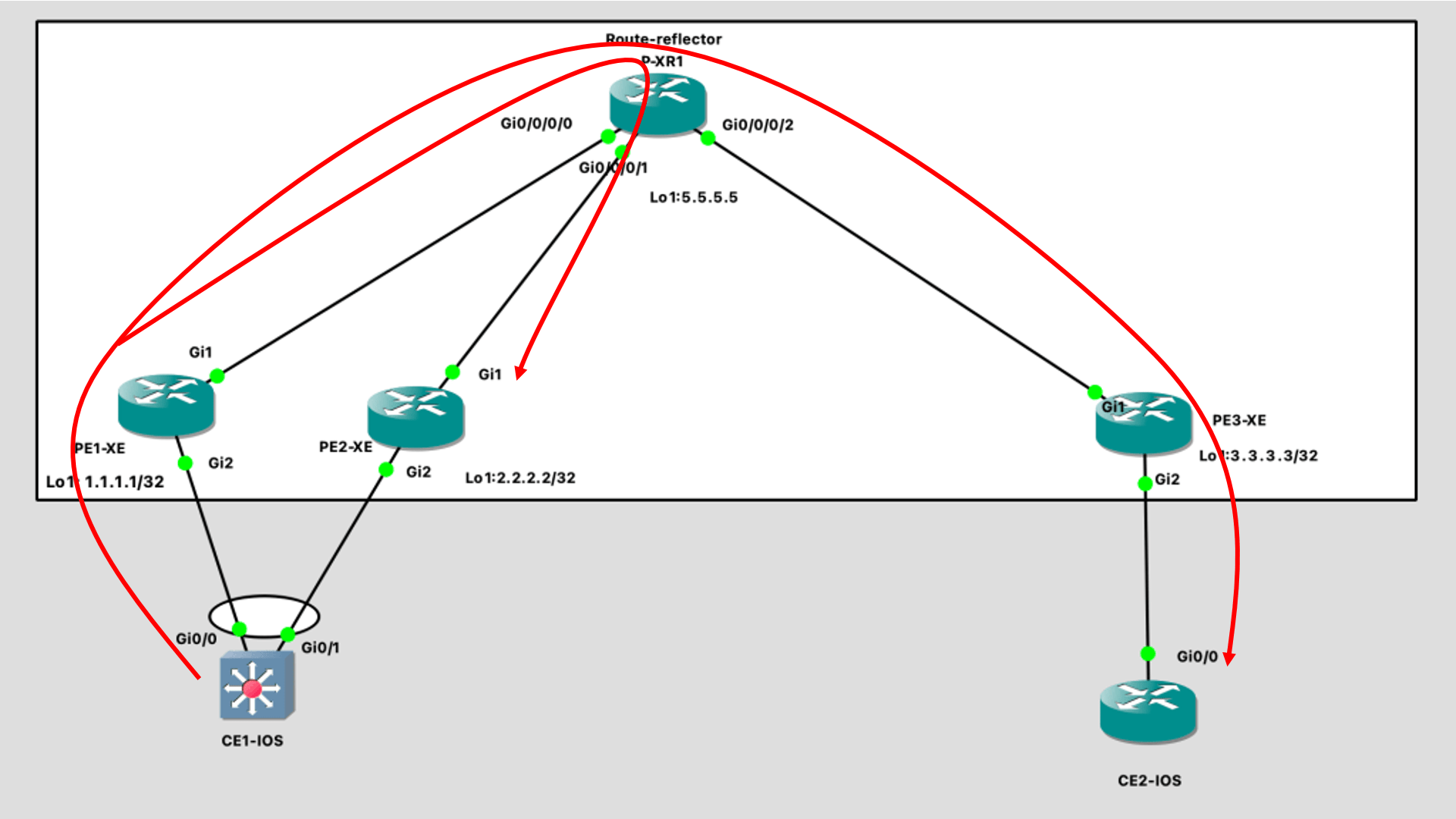
For BUM(Broadcast, Unknown unicast , Multicast ) traffic EVPN has a special handling. Lets understand how did the arp resolve in this situation. EVPN works to do ingress replication for all BUM traffic and with that they send it to all the EVPN peers, for example PE1 has two EVPN peers PE2 and PE3, If PE1 needs to forward any BUM traffic it will make two copies of that traffic and send it to PE2 and PE3, lets see this process in below steps.
STEP -1: CE1-IOS sends arp out for 20.20.20.2 IP which is configured at the other end of the EVPN network on CE2-IOS router.
STEP-2 : This request will be hashed to one of the interface on the CE1-IOS switch and reaches to PE1 in this case.
STEP 3 : PE1 needs to forward the traffic to its EVPN peers PE2 and PE3 on the basis of ingress replication list. You can check the ingress replication list on the router with following command. TYPE-3 route associated with the bridge-domain 10 is used for BUM traffic in EVPN. Here we can see that 2.2.2.2 and 3.3.3.3 are sending type 3 routes to PE1. So PE1 will be sending one copy each to PE2 and PE3.
PE1-XE#sh bgp l2vpn evpn
Route Distinguisher: 2.2.2.2:10
 *>i  [3][2.2.2.2:10][0][32][2.2.2.2]/17
                      2.2.2.2                  0    100      0 ?
Route Distinguisher: 3.3.3.3:10
 *>i  [3][3.3.3.3:10][0][32][3.3.3.3]/17
                      3.3.3.3                  0    100      0 ?
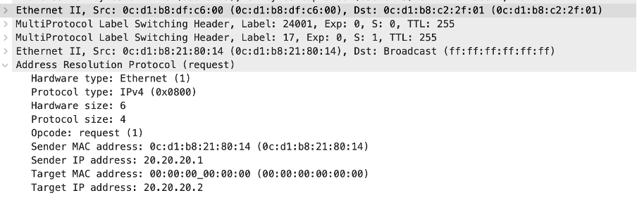
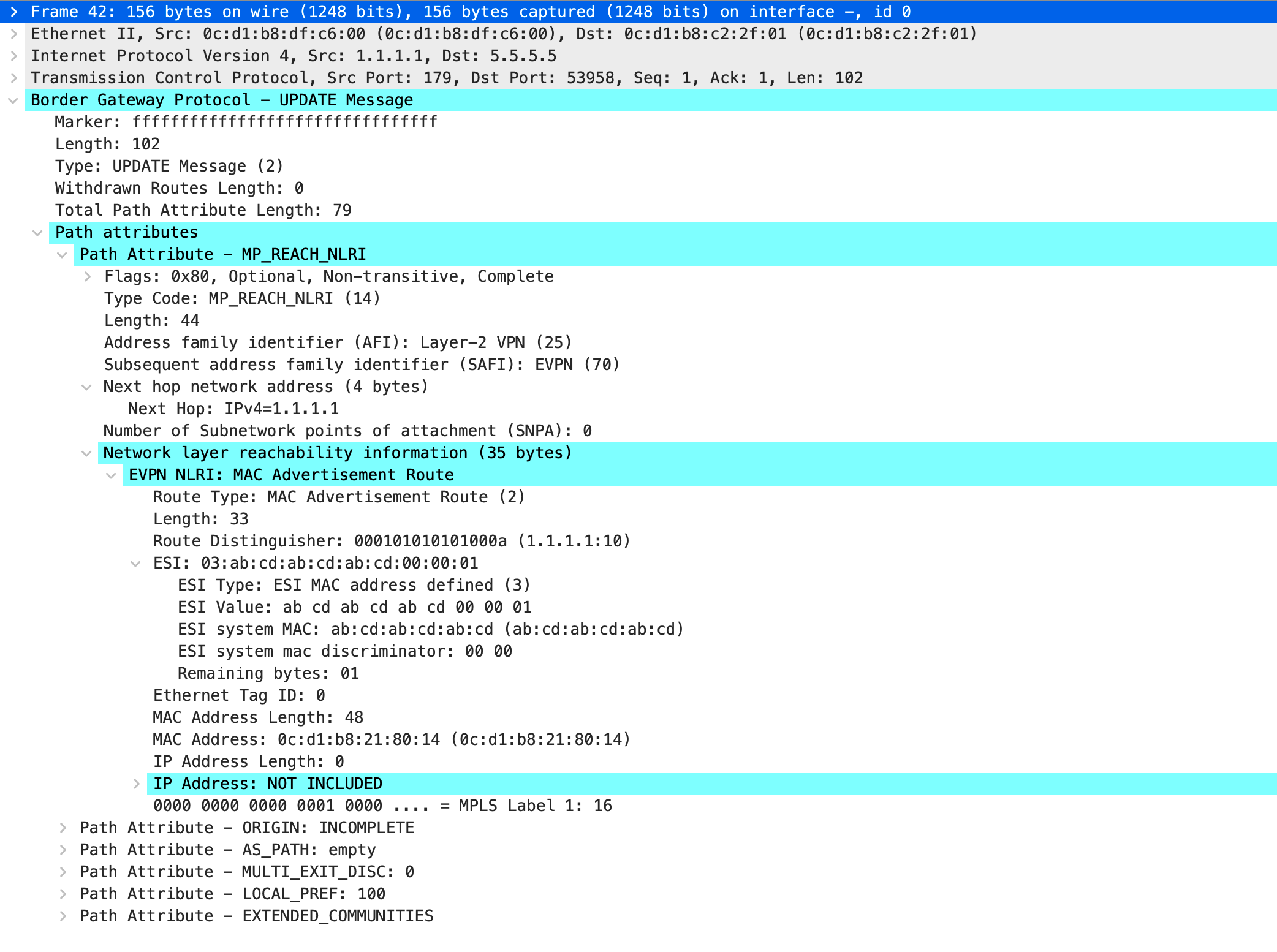
Below captures were taken on the link between PE1 and P1 router, we can clearly see that there are arp request replicated on the link.One is destined to PE2 and another is to PE3.As part of bgp updates all PEs will send inclusive multicast label to neighbor for the ingress replication and that label will be used to forward BUM traffic to those PEs. Here you can see that the PE1 router has used label (17 )to forward traffic to PE3 and label (17 and 16) to forward traffic to PE2 . The other label (24001 and 24000) are the transport label. Since the PE2 router is our multihome router so we do not want PE2 to forward the traffic back to CE1-IOS, this will create a loop. That is the reason that on top of inclusive multicast label we also have a ESI label, this label will tell the PE2 router that the BUM traffic is originated from the ESI which is connected to it, hence we need to drop the packet. And hence the ARP coming to PE2 from PE1 will be dropped at PE2 router.


STEP 4: Now we know that one copy of the ARP is dropped on PE2 and other copy is forwarded to PE3. The PE3 router will forward the ARP to the Bridge domain which is associated with the evpn where the arp is received.
STEP 5 : The response will follow the same process. The response should be unicast as the origin mac is present in the arp request. But the source mac will make in the bridge domain’s mac table only via BGP update (evpn process) and BGP update will take time . And until the BGP update doesn’t make it to the PE3 router by PE1 who has seen the a packet with the source mac (mac table gets updated only with source mac field), the arp response remains Unknown Unicast packet (BUM category). And hence PE3 will also create 2 copies of the response and sends it to PE1 and PE2.
STEP 6 : ARP response(Unknown Unicast- BUM) reaches to PE1 and PE2. But we know which router will forward the arp response to CE1-IOS. The DF router that is PE1.
PE1-XE#show l2vpn evpn evi detail
EVPN instance:       10 (VLAN Based)
  RD:                1.1.1.1:10 (auto)
  Import-RTs:        100:10
  Export-RTs:        100:10
  Per-EVI Label:     none
  State:             Established
  Replication Type:  Ingress (global)
  Encapsulation:     mpls
  Bridge Domain:     10
    Ethernet-Tag:    0
    BUM Label:       17
    Per-BD Label:    none
    State:           Established
    Access If:
    Pseudoports (Labels):
      Port-channel1 service instance 10 (16) (DF state: forwarding)
        Routes: 0 MAC, 0 MAC/IP
    Peers:
      2.2.2.2
        Routes: 0 MAC, 0 MAC/IP, 1 IMET, 1 EAD
      3.3.3.3
        Routes: 1 MAC, 0 MAC/IP, 1 IMET, 0 EAD


PE2-XE#show l2vpn evpn evi detail
PE2-XE#sh l2vpn evpn evi detail
EVPN instance:       10 (VLAN Based)
  RD:                2.2.2.2:10 (auto)
  Import-RTs:        100:10
  Export-RTs:        100:10
  Per-EVI Label:     none
  State:             Established
  Replication Type:  Ingress (global)
  Encapsulation:     mpls
  Bridge Domain:     10
    Ethernet-Tag:    0
    BUM Label:       16
    Per-BD Label:    none
    State:           Established
    Access If:
    Pseudoports (Labels):
      Port-channel1 service instance 10 (23) (DF state: PE-to-CE BUM blocked)
        Routes: 0 MAC, 0 MAC/IP
    Peers:
      1.1.1.1
        Routes: 1 MAC, 0 MAC/IP, 1 IMET, 1 EAD
      3.3.3.3
        Routes: 1 MAC, 0 MAC/IP, 1 IMET, 0 EAD
STEP 7: This is how the CE1-IOS router comes to know about the ARP and now the ICMP can be forwarded.
STEP 8 : Now the next step is that PE1 router will send a BGP update to PE2 and PE3 so that they can update the mac address in the bridge domain. Below is the packet that we will see in BGP update.
Conclusion:
EVPN is huge and no way I can put all about Multihome EVPN in this post without making it boring, lengthy and less useful. So I will stop this post now and will cover few more updates in my next post. I think for the basics we have enough details in this blog post and we can get started with it. Please keep reading.